
TACOM HQ®
Command Results
CAGE 834B9 SAM GHMFLBP9GGM3
“Incoming fire has the right of way." - Unknown
Structured Barrel®
Science and Engineering
At TACOM HQ, we do not just respect physics — we embody it. Every Structured Barrel is built on hard science: supported by comprehensive physical and mathematical proofs, and modeled through industry-standard FEA simulations using MSC/NASTRAN and LS-DYNA. Content has been independently modeled, reviewed, and validated with major contributions from a team of aeronautical engineers and from Cal (Cognitive AI Logic), whose collaborative insights supported the scientific and editorial integrity of this work.
This deep dive explores how principles like oscillations, thermodynamics, wave dynamics, and rigid body motion apply directly to barrel harmonics, heat distribution, and ballistic performance — both internal and external. To help demystify these principles, we’ve included illustrations, interactive tools, and variable models throughout this manuscript for real-time insight into how changes affect barrel behavior. A Structured Barrel is not an upgrade. It redefines the next generation of performance engineering.
Index
Section 1: Understanding Barrel Flexion as Waves
1.1 – Axial Stiffness
1.2 – Bending Stiffness
1.3 – Torsional Rigidity
1.4 – Natural Frequency
1.5 – Waveforms in Barrels
1.6 – Temperature and Waves
1.7 – Barrel Flexion and Waves
1.8 – Observable Harmonics
1.9 – Instrumental Proof
1.10 – Second Moment of Area
1.11 – Mathematical Proofs for Increased Stiffness
Section 2: Understanding Barrel Flexion as Heat
2.1 – Flexion and Energy
2.2 – Energy and Heat
2.3 – Heat Flow
2.4 – Thermal Expansion
2.5 – Thermal Expansion and Waves
2.6 – Variable Heat Q
2.7 – Material Failure
Section 3: Understanding Barrel Flexion Effects on External Ballistics
3.1 – Non-linear acceleration
3.2 – Ballistic Coefficient
3.3 – Drag
3.4 – Tip-Off
Conclusion
IP Statement
How it Works
1.1 Axial Stiffness
To understand why a Structured Barrel performs so differently, we first need to explore how barrel structure influences vibration, heat, and stability — and how traditional designs fall short — starting with axial stiffness.
Axial stiffness describes a structure’s resistance to stretching or compressing along its length when force is applied in the same direction. In simpler terms, it’s how much a structure “gives” under load. Mathematically, this relationship is defined by Hooke’s Law, where:
F = kx
Here, F is the applied force, x is the displacement (deflection), and k is the axial stiffness constant.
The spring example below illustrates two key truths:
• When force increases, displacement increases (direct relationship).
• When stiffness increases, displacement decreases (inverse relationship).

In barrels, axial stiffness determines how well the barrel maintains its shape under load — especially during the violent forces generated by firing. It is a function of:
• Cross-sectional area of the barrel (structural stiffness)
• Mass distribution (influenced by components like brakes or suppressors)
• Modulus of elasticity of the material (resistance to stretch and compression)
In mechanical systems like rifle barrels, shafts, and columns, axial stiffness is critical for maintaining alignment, structural integrity, and reducing vibration. It’s not just about withstanding force — it’s about controlling how that force moves through the system — in this case, the barrel.
While axial stiffness helps us understand how a barrel stretches or compresses under load, it doesn’t reveal the whole story. The next key factor is how a barrel bends — and that’s where bending stiffness comes into play.
1.2 Bending Stiffness
Unlike axial stiffness, which measures resistance to stretching or compression, bending stiffness describes a structure’s resistance to flexing under lateral force or bending moments — especially those introduced at the muzzle, along unsupported spans, or at force-transition points.
As shown below, force can cause vastly different deflections depending on how the material is distributed in relation to the direction of that force. The beam with more vertical mass — or structural height — resists bending significantly better.
Watch the full animation [here] to see bending stiffness in motion.

While flexion in simple beams can be calculated using classic closed-form equations, more complex geometries — like Structured Barrels — require finite element analysis to account for variable section shapes.
In general, bending stiffness is proportional to a barrel’s moment of inertia — a mathematical description of how material is distributed around its neutral axis. By increasing moment of inertia through intelligent structural geometry (rather than added mass), the Structured Barrel achieves dramatically higher resistance to bending — and therefore better alignment retention, vibration control, and shot consistency.
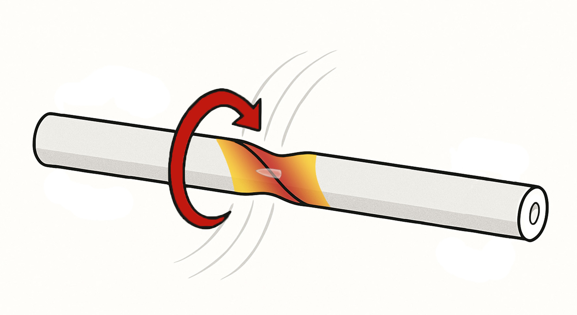
1.3 Torsional Rigidity
While bending and axial stiffness govern how a barrel flexes and stretches, torsional rigidity describes its resistance to twisting under torque. This becomes especially important when evaluating dynamic forces caused by bullet-barrel interaction and the added inertia of muzzle brakes, suppressors, or asymmetric contours — all of which can create rotational, whipping forces along the barrel’s longitudinal axis.
Torsional rigidity is governed by the polar moment of inertia — a measure of how mass is distributed radially around the central axis. Greater distribution away from the center increases resistance to twisting.
In barrels, torsional loads arise from:
• Rotational acceleration of the projectile (rifling engagement)
• Recoil impulse interacting with asymmetrical attachments
•Thermal gradients throughout the barrel, causing warpage (droop) and torque-induced deviation
Structured Barrels use precise, calculated geometries to increase torsional rigidity with little to no unnecessary weight gain. By controlling mass distribution around the centerline, Structured Barrels reduce angular displacement and restore rotational alignment more quickly after each shot. This is especially valuable in fast-twist barrels, heavy subsonic platforms, and suppressor-equipped systems, where torque-induced deflection can cause point-of-impact shift and other harmonic instabilities.
With axial, bending, and torsional stiffness now addressed, we turn to the structural characteristic that links all three: natural frequency — the rate at which a barrel wants to oscillate, and how to tame it.
1.4 Natural Frequency
Every object has a natural frequency — the rate at which it prefers to oscillate when disturbed. For barrels, this frequency is governed by three factors:
• Mass distribution (e.g., suppressors, tuners, or material profile)
• Structural stiffness (changes in length, diameter, or geometry)
• Material stiffness (modulus of elasticity — such as 416 stainless vs. chromoly steel)
These variables determine how a barrel resists deflection during oscillation — and they interact as part of a larger harmonic system.
A simple way to visualize this is through sound. When you strike a solid object — a tuning fork, a rod, or a barrel — the resulting pitch reveals its natural frequency. That pitch is the audible form of its mechanical vibration: the object flexing, rebounding, and oscillating until the energy is grounded or dissipated.

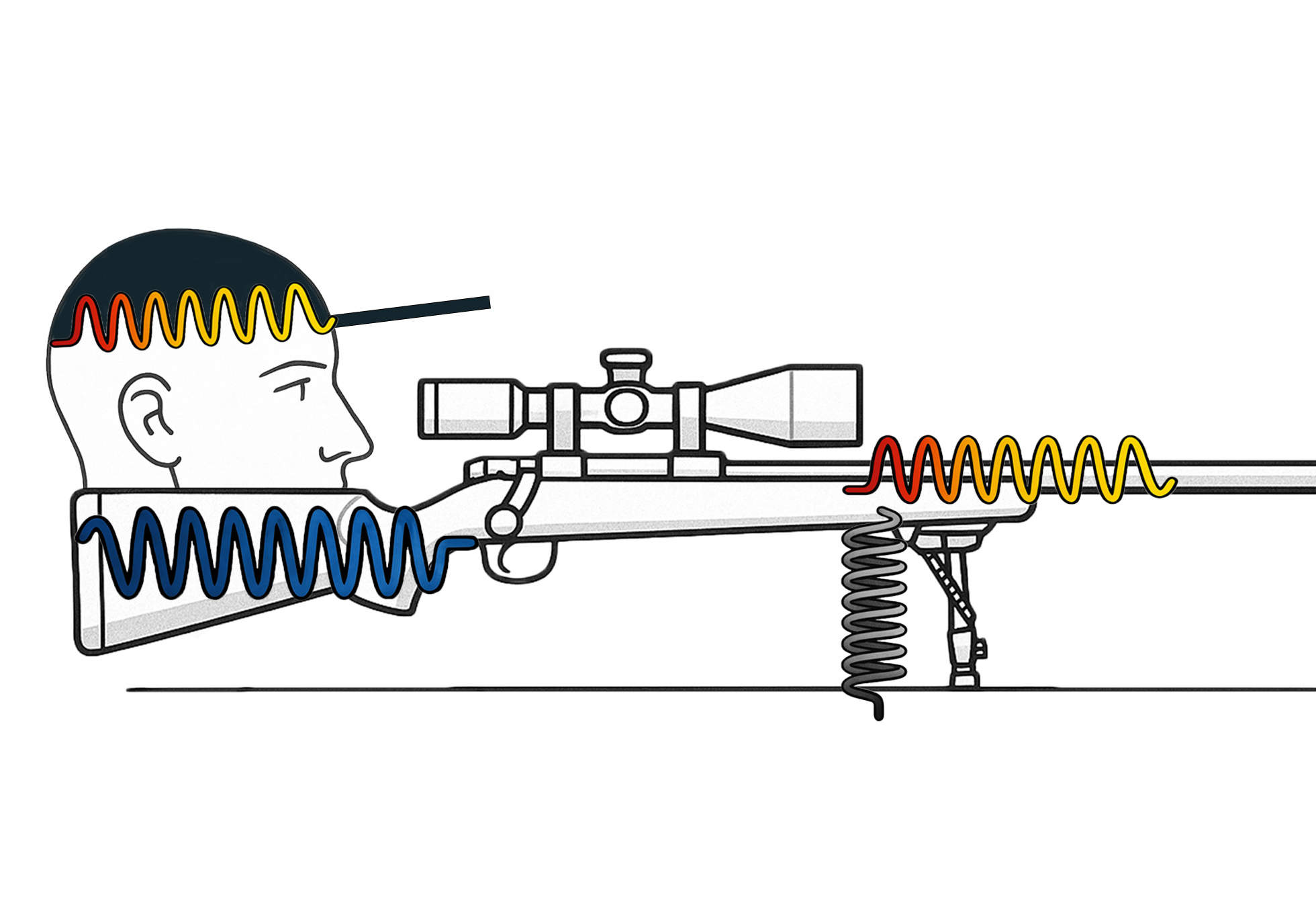
In rifles, though, natural frequency is not determined by the barrel alone. The entire firing system contributes:
• The stock or chassis interface
• The bipod or mount stiffness
• The ground interaction beneath the support system
• Even the shooter’s own input
Each of these acts like a spring with its own stiffness constant (k), all connected to the same vibrating body. These overlapping interactions alter how — and where — energy flows through the rifle system during recoil and shot exit.
Ideally, waves propagate cleanly through uniform, homogeneous mediums. But in firearms, mismatches in stiffness or contact points create irregular wave propagation, causing non-repeating oscillations, dissonance, and perceived vibration. This energy must dissipate — and it does so through grounding and friction, ultimately yielding group dispersion on target.
Understanding natural frequency is not just about making the barrel stiffer — it’s about tuning the entire system to minimize chaotic energy, and allow the barrel to return to a known, stable pattern, shot after shot.
1.5 Waveforms in Barrels
Vibrational chaos within a barrel isn’t confined to a single plane — it’s a blend of complex waveforms that manifest as three-dimensional motion. Two primary waveforms dominate: S-waves (shear or sinusoidal) and P-waves (compressive or longitudinal).
• S-waves move perpendicular to the direction of force, creating the classic ‘barrel whip’ — lateral flexion reminiscent of a guitar string under pluck.
• P-waves compress and expand along the axis of motion. They are generated by the violent pressure spike from expanding gases and the mechanical interaction between the bullet and barrel — as the projectile forcibly engages the rifling, it compresses the steel ahead of it.

These waves propagate at astonishing speeds — S-waves around 8,000 mph, and P-waves exceeding 13,000 mph — traversing the barrel multiple times before the bullet even exits the muzzle. This means the bullet’s path is shaped not just by the shooter, but by the barrel’s vibrational state — and the work being done to forcibly straighten a dynamic system. That very resistance amplifies wave interaction, compounding oscillations until the bullet exits.
When these waves interact, they don’t always cancel out — they often interfere:
• Constructive interference amplifies vibration, increasing energy and deviation
• Destructive interference cancels vibration, stabilizing the system
Without intentional guidance, these interactions become chaotic and non-repeating, generating irregular flexion and forcing each shot to exit at a slightly different point in the oscillation cycle — resulting in point-of-impact unpredictability.
Structured Barrels are designed not to eliminate these waves, but to shape and guide them. The geometric channeling created by the deep hole drills — precisely machined and intentionally placed — promotes predictable wavefront reflection and damping, coaxing the waveforms to follow a preferred path rather than bouncing erratically throughout its structure.
Instead of a barrel fighting itself, Structured Barrels behave more like tuned waveguides — with controlled interference zones, repeatable energy decay, and stabilized motion. This is conceptually similar to the science behind directional microphones, like shotgun mics, which guide waveforms through internal geometry to isolate and resolve signal from noise. Structured Barrels apply this principle mechanically, preparing the barrel to settle into a more predictable harmonic mode before the bullet exits.
Next, we examine how temperature interacts with wave propagation — altering density, elasticity, and ultimately, how energy moves through the system.
1.6 Temperature and Waves
The speed at which waves travel through a barrel isn’t constant — it depends on temperature. As temperature increases, atomic vibration intensifies and this increases the average distance between atoms. While this may seem like a high-energy environment, it paradoxically slows wave transmission, because atoms take longer to collide and pass along vibrational energy.
This relationship explains why wave speed is fastest in solids, slower in liquids, and slowest in gases. In solids, atoms are tightly packed, so vibrations transfer with minimal energy loss. In gases, particles are far apart and moving freely, causing greater energy dispersion and longer transmission times.

Temperature doesn’t change wave frequency — it changes speed, and therefore wavelength, as described by the wave equation:
v = λf
(Speed = Wavelength × Frequency)

In a heated barrel, these shifts in wave speed and wavelength influence vibration timing, harmonic convergence, and energy decay — especially over prolonged firing strings where temperature changes rapidly. This makes understanding material thermal behavior critical to controlling flexion, dispersion, and return to zero.
Structured Barrels account for this through engineered geometry — achieving critical gains in surface area and structural rigidity that preserve both stability and harmonic alignment, even as temperature fluctuates. The result is consistent, shot-to-shot predictability across a wide thermal envelope.
1.7 Barrel Flexion and Waves
These changes in material behavior, as heat flows from regions of high to low energy — and entropy increases — the barrel’s material properties shift. With each incremental degree rise in temperature, the medium’s ability to conduct waves subtly changes, as the steel undergoes infinitesimal phase drift toward a more fluid-like state. This is not full melting, but a measurable reduction in stiffness and energy transfer efficiency.
This affects sinusoidal S-waves and compressive P-waves that are repeatedly generated by violent mechanical forces like:
• Gas pressure at the breech and bore
• Recoil impulse
• Bullet interaction (rifling engagement, bore concentricity, and path straightness)
• Gravitational torque acting on a suspended, unsupported barrel length
These waveforms work in tandem to simultaneously push, pull, stretch, compress, and twist the barrel in highly dynamic patterns. Each mode of flexion propagates as a frequency of displacement, and these frequencies shift in response to localized temperature gradients.
Because S- and P-waves travel several times faster than the bullet, they wrap the structure in variable oscillation patterns. This can exaggerate the bullet’s interaction with the barrel — introducing new deflections, misalignments, and rotational accelerations. These effects are often perceived as barrel whip — the visible manifestation of constructive and destructive wave interference happening in a material that is no longer uniformly rigid.
In this way, flexion is not just a product of firing — it’s an evolving function of temperature, structure, and time, with the bullet caught inside the system’s harmonic feedback loop.
1.8 Observational Harmonics
Everything we’ve discussed so far — waveforms, flexion, temperature, and vibration — manifests in a simple, observable way on target: group size. And perhaps nowhere is this more clearly demonstrated than in ladder testing.
As round count increases, barrel temperature rises, altering stiffness, wave velocity, and harmonic behavior. Each shot adds incremental heat, subtly shifting the barrel’s vibrational mode and wave propagation characteristics — often enough to cause the point of impact to drift. This is why even consistent loads may open up as the string progresses.
Ladder tests, designed to identify optimal powder charges or node windows, inadvertently expose the influence of thermal and harmonic stability. Within a tight charge window, some groups cluster tightly — these represent moments when barrel and load are momentarily “in tune.” Just outside that window, harmonic misalignment causes shots to scatter — despite identical external conditions.
In this way, ladder tests aren’t just load development tools — they are diagnostic instruments that measure the rifle’s sensitivity to structural and vibrational inconsistency.
Rifling geometry and barrel condition influence these inconsistencies, but the difference is typically marginal — on the order of 1–2% in even a “shot-out” barrel. Custom handloads further mitigate error from principal axis tilt and pressure curve variability. So when we observe meaningful differences in group size or point-of-impact between load variants, it suggests other forces are at play.
One common shooter response is to compensate optically — zeroing to the observed point of precision. If Load A consistently centers at (x, y) and Load B at (x+1, y+1), the shooter may dial out that offset and call it zero. But that zero is now calibrated to a specific thermal and harmonic state, and will shift again with:
• Changes in ambient air temperature
• Sun exposure
• Round count over time
These changes influence barrel temperature, and thus material stiffness and flexion behavior. Barrels that exhibit noticeable horizontal or vertical dispersion under small thermal shifts are likely responding to wave amplification, structural resonance, or material expansion asymmetry.
To isolate the role of barrel flexion, we consider only the vertical plane in the below illustrations:

This is a 1.35″ diameter barrel. The next image is this same barrel, magnified 8×.

The light gray line above the barrel represents only 0.001” of flexion — near-imperceptible, yet mechanically significant.
Using a 24″ barrel with a single point of deflection 6″ from the chamber, the following vertical shifts at 100 yards were calculated based on various flexion values:
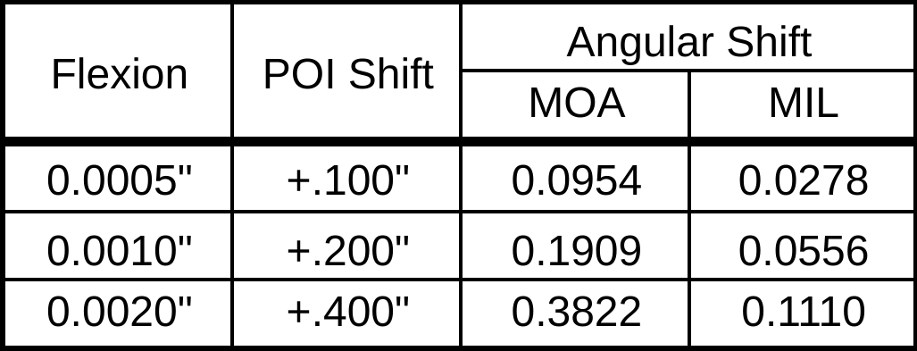
All of these values are easily discernible in a scope — yet originate from movements nearly impossible to perceive in the barrel with the naked eye. A difference of just 0.0005″ (half a thousandth) in flexion corresponds to a 0.100″ shift on target — an amount one-third smaller than the thickness of a human hair, but measurable across 100 yards.
These calculations don’t account for:
• Variations in CGI offset
• Thermal gradients during or exceeding a 5-shot string
• Multiplanar forces from bullet-barrel engagement (which impart xyz flexion vectors)
Thus, while ladder tests may not always isolate small changes like 0.0005″ vs. 0.0010″ flexion, they expose the Gaussian curve of dispersion — revealing both visible POI drift and the underlying harmonic sensitivity of the system.
What appears as “minor group growth” may, in fact, be the visible result of unseen mechanical movement, among other variables.
1.9 Instrumental Proof
Skeptics often reference high-speed footage as proof that barrels “don’t move.” At first glance, these videos seem compelling — no visible motion, no whip, no deformation. But this belief falls apart under scrutiny, for one simple reason: the limits of observation are not the limits of reality.
Visual systems — from high-speed cameras to optical scopes — operate within two competing constraints:
• Resolution (how much detail the system can capture)
•Magnification (how large the subject appears)
When you increase magnification to focus on the barrel, you lose resolution and temporal precision. When you maximize resolution (e.g., 100,000+ FPS), you must sacrifice magnification, field of view, or both. As a result, most high-speed footage:
• Captures flexion blurred across frames
• Misses the sub-millisecond elastic return between shots
• Fails to differentiate micro-deflection from camera shake or background noise
The scale of flexion we’re discussing — 0.001″ or less — is often smaller than the pixel size of the sensor. It’s like trying to measure the width of a human hair from a mile away with a Polaroid.
Some skeptics turn to oscilloscopes and accelerometers — hoping to “measure vibration directly.” While this is technically possible, it introduces a paradox: In order to measure flexion, you must isolate the barrel from the system — but doing so creates an artificial condition that no longer reflects real-world use.
Here’s why:
A barrel is not a standalone object. It is part of a dynamic system, including:
• Stock or chassis
• Receiver bedding
• Muzzle devices
• Bipods, tripods, or shooting bags
• Shooter input (shoulder pressure, grip torque, breath)
Each of these has its own spring constant, natural frequency, and harmonic decay. Attempting to isolate the barrel is not only extremely complex as each attachment affects behavior, but to get a “clean reading” strips away the very forces that contribute to real-world dispersion.
Worse yet, accelerometers mounted on the barrel may:
• Add mass at non-neutral nodes, altering flexion behavior
• Fail to resolve motion in orthogonal planes
• Be overwhelmed by gas jet shockwaves and combustion harmonics
We may not always observe barrel flexion directly — but we regularly see its effects:
• Group widening as barrels heat
• POI drift over long shot strings
• Micro-adjustments in load development reflected at 100–1,000 yards
In other words, Structured Barrels deliver repeatability — consistency not just in theory, but on target. And that brings us to a key structural principle in understanding and managing barrel flexion and wave behavior: the Second Moment of Area — the geometric foundation of a barrel’s resistance to bending.
1.10 Second Moment of Area
Recall, the S and P waves produced from gas pressure, recoil, and bullet-barrel interaction inject enormous energy into the system — compressing, stretching, and twisting the barrel at high frequency. As these linear and radial forces travel the length of the barrel multiple times, they induce flexion with corresponding accelerations about the barrel’s center axis. While this motion is influenced by a barrel’s moment of inertia, the magnitude of flexion is governed by its Second Moment of Area — a geometric measure of how effectively its cross-section resists bending.
To visualize how a barrel physically responds to these dynamic loads, we turn to structural simulations below developed by Al Harral, a former structural analyst at Lawrence Livermore National Laboratory with three decades of experience in complex system analysis. These simulations were conducted using LS-DYNA, a powerful Finite Element Analysis (FEA) tool used to model dynamic and static loading in mechanical structures.
Importantly, the following simulations assume a perfectly straight bore and amplify displacements significantly to make vibrational behavior perceptible. As Harral writes, these visualizations show how:
“Forced deformations from the high-pressure gas and recoil cause the muzzle to change where it is pointing at the target when the bullet exits the muzzle… The recoil and bullet motions ‘pull’ the rifle barrel to a new shape.”
The takeaway: a barrel with superior stiffness exhibits far less deflection from gas pressure and recoil alone — a fundamental property that defines the behavior of waveforms and the precision of the system.
Perhaps most revealing is Harral’s observation:
“The vertical amplitude of vibration is more heavily excited than the horizontal… because the center of gravity of the rifle is located below the barrel’s centerline, and the bullet’s travel down the barrel causes a vertical turning moment about the rifle’s center of gravity. [This makes] the vertical vibration most important.”
This vertical axis is crucial to understanding real-world dispersion patterns, as torsional acceleration exerted by the bullet attempts to straighten — or unscrew — the barrel, shifting point of impact away from point of aim. This phenomenon underlines the geometric principle realized in Structured Barrels.
Simulations model a 6mm rifle with a 22″ 416 stainless barrel with no rifling and straight taper from 1.24″ at the breach to a 0.935″ DIA at the muzzle. The modeled barrel, action, stock, scope, scope mounts, brass weight, etc. came within approximately 7oz of the real thing. Mesh detail is provided, consisting of 17,196 nodes and 12,080 elements. Despite only half of the mesh being used in calculations, each shot calculation still took about an hour to set up and simulate, outputting about 2.5Gb of data.


Mode 1 – Cantilever Bending
82Hz
Mode 2 – 1 Node Bending
406Hz
Mode 3 – 2 Node Bending
1050Hz
Mode 4 – Axial Extension
1756Hz
Mode 5 – 3 Node Bending
1984Hz
The above simulations demonstrate how different frequencies manifest as physical movement along the barrel’s length. It is important to note, while modes 1, 2, and 3 are shown in a single plane, they may exist in other planes, and exemplary modes 1-5 are – all – excited, simultaneously when firing a round. While the higher frequency modes have extremely small amplitudes, it is difficult to visualize just five modes acting at the same time, let alone many many more.
The amount of resistance a shape can exert to bending about its geometry on a particular axis is its second moment of area, and this is dependent on the area and material distribution to the axial moment. Cross-sections of an object that locate the majority of the material far from the bending axis have larger moments of inertia, making said cross section considerably more difficult to bend when force is applied. This is one reason I-beams, and not rectangular bars, are commonly used in structural applications, because they position sufficient mass in both x-y planes to resist force and deflection. Since Structural Barrels are analogous to I-beams reinforcing the bore in multiple planes, this creates a geometry that resists bending in multiple planes.
1.11 Mathematical Proofs for Increased Stiffness
We can mathematically define this geometry and the Second Moment of Area (J) for a cross section of a barrel as
J = ∫ r² dA; where r² = x² + y² and dA = 2π • r dr
J = ∫ r² • 2π • r dr = πR⁴/2
Perpendicular Axis Theorem Jz = Ix + Iy; barrels are a symmetric object
Ix = Iy = πR⁴/4
Evaluating the Second Moment of Area per Unit of Area — Rod (conventional barrel) versus Tube (Structured Barrel)
SRod = IRod / A; where A is the area πR² = R²/4
STube= (IRod/ARod) – (ITube/ATube) = R²(1+x²)/4; where x = r(inner) / r(outer)
We see as the x limit approaches a 1:1 ratio to the radius R in the STube, a tube exhibits twice the stiffness, but this also requires an infinitely small radius. Stiffness, in this context, governs how much a barrel will bend or resist displacement under the same applied forces. It’s a function not just of material, but how far that material is distributed from the bending axis. These equations indisputably demonstrate a body of equal mass positioned farther from the bending axis has a larger moment of inertia, making it significantly more difficult to bend. This is further corroborated by an independent aeronautical CEL analysis using MSC/NASTRAN that found +50% greater stiffness in a simulated barrel of the same weight.
Using R²/4, or the stiffness per unit area, we can evaluate this to a barrel that is X% larger, and the difference between a big and small barrel may be simplified as R²(1-X²)/4. Since X is the difference between two barrel diameters as a percent, it is important to note this value is driven by a square. So, procuring a 1.65″ blank versus a 1.35″ blank yields 22.50% more (free) stiffness. Because stiffness scales with the square of radius, small increases in diameter yield disproportionately large improvements in resistance to bending. Compound this with added structural rigidity, and this value becomes rather significant. It is no secret bull barrels are typically more precise than a standard profile. Mathematically, this is one reason why.
2.1 Flexion and Energy
Now that we understand flexion as waves, let’s now define its heat byproduct. Gas pressure, recoil, and the interaction between the bullet and the barrel are all exemplary forces that act on a barrel. The equation to describe force is the multiple of mass and acceleration, the rate velocity changes in respect to time. Since barrels have mass, the work done to accelerate a barrel onto a sinusoidal wave about its center axis via tensive and compressive forces requires energy. These relationships are described by the below equations:
v = x/t
a = dx/dt (rate of change)
F = m•a
W = F•Δx
ΔK = W
K = Energy (kinetic)
2.2 Energy and Heat
Since energy is proportional to the work done on a system from an initial state to a final state (the First Law of Thermodynamics), and the Law of Conservation of Energy dictates that energy can neither be created nor destroyed, the work done on a barrel to accelerate it about its center axis due to flexion requires substantial energy. This energy creates atomic friction and thereby heat.
This raises barrel temperature, and while atomic vibrational rates vary per atom, Maxwellian distribution reveals thermal energy raises the average vibrational speed of all atoms, even in the presence of non-uniform heat gradients across the barrel. The average kinetic energy of the barrel’s atoms define its temperature and thermoelastic behavior — a state where stiffness and stress-strain relationships become increasingly temperature-dependent. Each fast, follow-up shot thus encounters a barrel not only hotter, but softer, slightly more unpredictable, and increasingly chaotic.
2.3 Heat Flow
With every shot delivers another surge of energy — not just into the bullet’s motion, but into the barrel’s body itself. This energy does not remain static; it transforms into heat and spreads outward from the bore and from the chamber. To understand how heat physically migrates through a barrel, we must turn to heat conduction — the process by which thermal energy transfers from regions of high temperature to regions of lower temperature, atom by atom.
This flow is not instantaneous. Nor is it uniform.
In cylindrical bodies like barrels, heat flows radially outward, from the inner bore radius (r₁) to the outer surface (r₂). The rate at which this occurs depends on several variables:
• The temperature differential between these layers (ΔT),
• The material’s thermal conductivity (k),
• The contact area available for transfer (A = 2πrL),
• And inversely, the thickness of the material the heat must traverse (Δr).
This relationship is described by the heat conduction equation for a hollow cylinder:
Q = 2πrkL • (T₁ − T₂) / ln(r₂ / r₁)
Where:
Q = heat transfer rate in watts
r = radius at which the evaluation is made
k = thermal conductivity coefficient
L = length of the barrel segment
T₁ − T₂ = temperature difference between the inner and outer surfaces
ln(r₂/r₁) = natural log scaling for radial spread
This equation quantifies the energy required to raise the outer wall (r₂) to a target temperature (T₂), starting from an internal condition (T₁), and reveals something critical: thicker barrels resist rapid heating not solely due to thermal mass, but due to geometry.
As r₂ increases, the surface area for heat conduction grows linearly, while the conduction path (Δr) grows logarithmically. Thus, increasing a barrel’s outer diameter and internally structuring it extends the conduction path (Δr), while reducing, equalizing, or only marginally increasing mass—depending on the selected deep-hole geometry.

This geometry creates a thermal guide: the narrow wall between each internal channel and the barrel’s outer diameter, promoting unrivaled thermal stability during repeated or sustained fire. As excess energy passes from atom to atom, each retaining a slight vibrational increase, the excited electrons emit thermal radiation in all directions. Since Structured Barrels exhibit over 300% more surface area, they offer significantly more surface to radiate and evacuate heat from the system, rather than trapping it and relying solely on atomic absorption. Combined with the thin-walled segments acting as internal heat sinks, and the forced convection created by the low-pressure wave trailing the bullet through the muzzle, the result is substantial thermal control and endurance.
These dynamics matter because temperature changes do not remain isolated or isometric—they initiate measurable material changes. A barrel’s geometry and elastic behavior begin to shift as localized regions expand differentially. In other words, the conduction curve sets the stage for thermal expansion. The faster the inner bore rises in temperature relative to the outer wall, the greater the risk for asymmetric stress. Thus, rapid heat flow—and ultimately, rapid heat evacuation—preserves material stiffness throughout the barrel without introducing unwanted variable change shot to shot.
From microscopic friction to macroscopic flexion and expansion, heat flow is not merely a thermal event. It is unequivocally a structural one.
2.4 Thermal Expansion
The structural changes realized in the increase of atomic vibrational speeds directly impacts the kinetic energy of individual atoms, and thereby the macroscopic properties of the material. In solids, atoms are densely packed and bound by strong interatomic forces. These atoms primarily vibrate around their equilibrium positions without migrating past one another, giving solids a definite shape and volume.
These vibrations are governed by the Lennard-Jones Potential, which models the potential energy between two atoms as a function of their separation distance. Visualized like two masses connected by an asymmetric spring, the potential well is deeper and steeper on the compression side — meaning it requires significantly more energy to force atoms closer than to let them drift apart. As a result, atoms spend more time slightly separated than compressed during vibration, which shifts their average spacing outward as temperature increases.
This phenomenon at the atomic scale causes solids to expand when heated at the macroscopic scale, and since most crystalline solids are isotropic — expanding equally in all directions — their proportions stay consistent while absolute dimensions increase. The relationship is described by the thermal expansion coefficient, which defines the fractional change in size per degree of temperature rise. This is thermal expansion: the tendency of matter to change in shape, volume, or area in response to temperature.

The potential curve illustrates how atoms favor a certain equilibrium distance but shift outward as vibrational energy (temperature) increases.
To translate these atomic principles into something measurable, the following interactive calculator estimates bore diameter growth due to thermal expansion. The user inputs an initial bore diameter, a starting temperature, and a final temperature — revealing how even sub-degree changes can exceed 0.0001” of radial movement.
The physics of thermal expansion is defined by:
ΔL = αL • ΔT
Where:
• ΔL is the change in length
• α is the thermal expansion coefficient
• L is the starting length
• ΔT is the change in temperature
Using a thermal expansion coefficient of 6.5 × 10⁻⁶ in/°F for 416 stainless steel, this equation reveals that temperature affects not only barrel length but also outer diameter and most critically its bore diameter. Superior bullet manufacturers segregate by tolerances well below 0.0001”, and this margin can be exceeded by something as simple as ambient air temperature, sun exposure, or a prolonged firing string.
However, this formula assumes a uniform thermal field, which is rarely the case. In real-world barrels, heat is distributed unevenly across both the longitudinal and radial axes. This creates thermal gradients — layered zones with distinct temperatures, elastic behaviors, and sometimes even microstructural phase changes. As each layer expands differently, it creates internal stress fields that subtly shift the barrel’s geometry, alignment, and vibration response. Thus, thermal expansion is not just a matter of “stretch” — it is a shift in internal architecture, subtly altering how the barrel moves, resonates, and ultimately wears with every shot.
2.5 Thermal Expansion and Waves
This thermal expansion decreases a barrel’s density as its atomic arrangement increases, and while energy input may be uniform per calorie, its effect is not evenly distributed along the barrel. Longitudinal and radial temperature gradients emerge, driven by localized hotspots near the throat, muzzle, and radial cross-sections. Since mass remains constant, yet the average distance between atoms increases, the time and distance required for one atom to transfer vibrational energy to the next also shifts — and shifts differently across each gradient.
The result? A medium whose wave-transmission characteristics are no longer constant. Thermal expansion disrupts the uniformity of stiffness, propagation speed, and even resonance. In essence, the structure becomes the arbiter of its own vibrational response — altered shot by shot.
As discussed in Section 1.6, thermal energy and wave behavior are inseparably linked. Together, they dictate how a barrel absorbs, stores, and transmits the impulses of recoil, gas pressure, bullet interaction, and gravitational torque. Barrels are not static. They are thermally alive — continuously reshaped by changes in temperature.
2.6 Variable Heat (Q)
To quantify thermal energy transfer within a barrel, thermodynamics uses the equation:
Q = mcΔT
Here, Q represents heat flow — positive for heat gain, negative for heat loss. While m is the material’s mass, and c its specific heat capacity: the amount of energy required to raise one gram of the substance by one Kelvin. Crucially, c is not fixed. Like stiffness and modulus, it varies with temperature.
At the atomic scale, added energy is distributed among translational, rotational, and vibrational motion. Lower temperatures yield less internal motion, meaning the material has greater potential to absorb energy and to be excited. As temperature increases, atoms already in motion require increasingly more energy to accelerate further, and thus specific heat capacity rises. This increase compounds the material’s ability to conduct and retain heat, making the barrel more thermally dynamic with each shot.
While Q may exert minimal influence under light firing, prolonged sequences introduce non-linear accumulation:
Q₁ + Q₂ + Q₃ + … + Qₙ
Each shot doesn’t simply add more heat — it adds more and more heat into a changing system. The initial Q₁ stems largely from detonation, pressure, and friction. But subsequent Qₙ contributions stem increasingly from internal atomic friction. As the material heats, stiffness degrades, making the barrel more susceptible to force — and inciting higher-amplitude oscillations. More motion means more flexion. More flexion means more heat. Thus, the system enters an energy loop, where mechanical deformation and thermal accumulation feed each other — driving the barrel further from equilibrium with each shot.
Ultimately, this rising Q injects enough energy to not just alter stiffness, but to initiate (potentially permanent) thermal deformation. For some cartridges, this threshold may be reached in as few as 10 rounds. At this point, Q is no longer just a measure of heat — it becomes a signal of system fatigue and the onset of material failure.
2.7 Material Failure
Material failure in barrels starts not as visible damage, but at the atomic scale — where elevated temperatures and repeated stress subtly erode the structural bonds that define hardness, tensile strength, and elasticity.
Metallurgy, the domain for metallic material science, examines atomic structure to describe material properties like hardness, tensile strength, and elasticity and methods to enhance the limits of metals and metallic alloys. The principle of steels are alloys, consisting of a mixture of metals for greater strength or corrosion resistance. For example, stainless steel is purposely formulated to resist oxidation, but each blend is tailored for specific conditions like salt water or for machinability.
The current standard for barrel manufacturing uses 416 stainless or Chromoly for added strength. Both comprise iron, carbon, chromium, and (sometimes) molybdenum, but the small fractional percent additions of elements like phosphorous and manganese in 416 improve machinability and hardenability, respectively. In other words, the incorporation of each element yields unique changes to its final properties.
Manufacturing alloys to the correct compositional standard requires precision and craft. Small deviations in ratio or in the rate to cool dramatically affects the material’s atomic structure. Solidification creates strong bonds with neighboring atoms, forming unique patterns and structural elements called grains. Crystalline grain structures vary in shape and size as atoms settle from a high energy Austenite liquid state to a low energy ferrite or Martensite state. Changes in atomic orientation create grain boundaries, and this too alters an alloy’’s material properties.
Generally, smaller the grain, stronger and more resilient the material is to stress with each grain boundary inhibiting thermal conduction and atomic dislocation. The interlocking of these atoms into grains though is imperfect, and while heat treating, cryogenics, and surface hardening serve to alter grain structure, repair atomic misalignment caused by micro voids or tears, or diffuse atoms into the crystalline structure, respectively, defects in crystal lattice patterns are the failure modes in alloys. Dislocations enable atomic planes to sheer – gliding or slipping past each other, even at low stress values.
Detonation and bullet-barrel interaction generate axial, longitudinal, and torsional wave patterns of varying magnitudes and frequencies that uniquely interact each grain structure due to their unique shape, size, and orientation. Atomic imperfections within each gain structure yield dislocations allowing atoms to slip, generating friction. This slippage occurs as far as its grain boundary before a new frequency pulls the weak lattice to a new position. As vibrational amplitudes increase due to heat, atoms are driven further apart, weakening interatomic cohesion – further altering wave behavior and, ultimately, grain structure.
This thermal agitation accelerates the breakdown of strength-bearing structures, and unlike elastic deformation, thermal degradation is unidirectional — it cannot be undone by cooling. It is a structural loss, not a temporary shift.
When the internal energy of a flexion impulse exceeds the material’s ability to elastically respond — given its temperature moment — failure occurs. The earliest sign may be molecular dislocation; the latest, fire cracking or throat/bore erosion. Either way, the material has crossed its thermomechanical limit.

3.1 Non-linear Acceleration
Now that we understand the internal effects of barrel flexion, we segway to its external effects. Extreme gas pressure, recoil, and bullet-barrel interaction inject enormous asymmetric energy into the barrel. Contrary to common belief, asymmetry is a common and natural consequence of barrel manufacturing. Tool wear, thermal flexion, and chip evacuation in deep-hole drilling introduce average tolerances of 0.001–0.0025” per inch. These deviations are rarely linear. Bore straightness may taper in multiple directions across its length, so the offset often increases exponentially with depth.
Accurately measuring such deviations is expensive. To compensate, manufacturers often turn the barrel’s exterior profile using the two ends of the imperfect bore to “match” concentricity. Yet even a hypothetically perfect bore is still subject to barrel droop — the gravitational tendency of a suspended rigid object to deflect, described by torque (τ = r × F). This downward deflection pulls the bore off the longitudinal centerline.
Though these offsets may appear insignificant in scale, Newtonian physics (F = ma) reveals that even subtle asymmetry causes uneven acceleration. And given the immense forces released during detonation — enough to accelerate the barrel’s mass to measurable velocity (K.E. = ½ • m • v²) — these minor imperfections can scale into measurable performance losses.
To visualize the barrel’s dynamic response, we turn to Al Harral, structural analyst at Lawrence Livermore National Laboratory:
“The barrel [itself] is initially slightly deflected downward due to gravity [torque]. When the round is fired, the [bullet and] pressure tends to straighten the barrel. As the barrel straightens, it over-shoots in the upward direction and this adds to the excitation of the Mode 1 vibration. As a side note, the axial extension vibration mode is also probably heavily excited.” — Al Harral, Barrel Tuner Analysis
No system is perfectly rigid. A projectile accelerates through a constantly moving, expanding, and contracting barrel. This invokes irregular stutters — micro deflections — as the bullet briefly expends energy to straighten segments of an imperfect bore before continuing forward. These stutters manifest as dynamic deflection patterns that rob the system of energy otherwise dedicated to consistent acceleration and higher muzzle velocity.
These concepts are further examined in Ep. 057 of the Hornady Podcast: “One Hole Groups? Dispersion.”
3.2 Ballistic Coefficient (BC)
Accelerating the barrel not only consumes energy for higher muzzle velocities, it also lowers a bullet’s ballistic coefficient (BC), a dimensionless ratio that describes drag. Higher the BC, the more efficiently a bullet resists drag from air resistance and retains its velocity over distance. Drag, the aerodynamic force opposing an object’s motion through a fluid like air, is influenced by shape, surface area, orientation, and spin.
Ballistic computation typically treats a barrel as a static object and a bullet as a point mass centered on its center of mass, an infinitesimal location where all mass is considered concentrated. However, barrels are *not* static and bullets are *not* point objects. Specifically, bullets are three-dimensional, rotationally dynamic bodies affected by the launch conditions within a dynamically moving barrel. The barrel’s motion during a shot — particularly deflection at the muzzle — imparts not just translational velocity, but angular momentum that causes the bullet to rotate or “tip off” about its center of mass.
This tip-off introduces yaw (ψ), nutation (3), and precession (4) — rotational motions that shift the bullet’s longitudinal axis away from its velocity vector. These changes increase drag and degrade the effective BC. Even a well-balanced bullet launched from a vibrating or imperfectly aligned barrel may undergo complex motion throughout flight, making theoretical BC predictions difficult.
The following excerpt from Sierra Bullets’ *Section 2.4: Lessons Learned from Ballistic Coefficient Testing* reinforces this reality:
“Theoretically, the BC of a bullet depends only on its weight, caliber, and shape. But in a practical sense, the measured BC of a bullet also depends on many other effects. The gun can affect the measured BC value in two important ways: spin stabilization and tip-off moments. […] As the bullet flies, the point rotates in a circular arc around the direction of the velocity vector. Coning motion results in increased drag on the bullet, and any firing test method then yields an effective BC value for the bullet that is lower than the theoretical value. We have never been successful in accurately predicting BC values […] by any method other than firing tests.”

1. Longitudinal axis
2. Velocity vector
3. Nutation
4. Precession
ψ Yaw
3.3 Drag
Tip-offs and the resulting coning motion of the projectile affect two critical variables in the drag equation used by ballistians to calculate a theoretical Drag Force — (Cd) and (A):
D = 1/2ρv² • Cd • A
Where:
• ρ is air density
• v is velocity
• Cd is the drag coefficient
• A is the cross-sectional area
When a bullet exits the muzzle with its center axis misaligned from its velocity vector — even slightly — its cross-sectional area increases. This raises its drag coefficient, and unlike the ballistic coefficient (BC), which improves performance when higher, a large drag coefficient increases the resistive force acting on the bullet during flight. These are measurable, aerodynamic variables that may be expressed in both angular and linear terms.
Using a widely-accepted empirical model to calculate drag coefficient, small increases in θ preserves quadratic approximation:
Cd(θ) ≈ Cd₀ • (1 + k + θ²)
Where:
• θ is yaw (ψ) angle
• k is about 0.02, a known constant used in ballistic modeling of slender bodies, like bullets
While this expression simplifies computational requirements, neglecting factors like unsteady flow, Mangus effect, and transient pressure zones, which require a proper 6DOF model, it still offers valuable first-order insight and relevancy to examine tip-off as a variable caused by structural dynamics at the muzzle.
3.4 Tip-Off
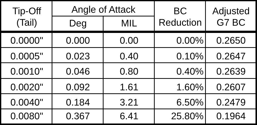
To quantify drag from a tip-off, we analyze a common 1.25-inch .308 175gr SMK round with a 0.265 G7 BC. Specifically, we will subject the bullet to small angular deflections (using the same values modeled in Section 1.8 Observable Harmonics) to derive the resulting yaw angle to calculate the increase in drag and thereby loss in BC.
Furthermore, instead of modeling the bullet as a point mass per industry standard, we will consider it as a rigid, rotating body. This allows us to convert tail displacements from inches into angular deflection, which can then be used to compute BC degradation.
Below, we see small tip-off values, even under 0.001″, can produce measurable angular deviations that have a meaningful impact on BC despite being almost imperceptible to the naked eye.
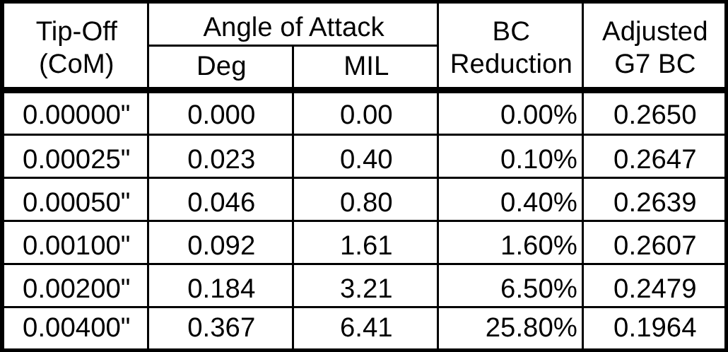
While relevant, the previous tip-off analysis assumes a simple geometric relationship where the tail is aligned with the velocity vector and only the nose deviates slightly to introduce yaw (ψ). This simplified model assumes bullets pivot at the tail to relate lateral offset to angular deflection across the full bullet length (L). However, in reality, rigid bodies do not rotate about their ends. In classical dynamics, objects rotate about their center of mass (CoM) when subjected to external force. This distinction is critical.
When the bullet reaches the muzzle, the front half is still mechanically coupled to the barrel’s bore and traveling in its direction of motion. Once the rear half reaches the crown at the muzzle, the front half is free to move while the rear is still susceptible to barrel movement. If the barrel is flexing — even by the smallest amount — it can apply a rotational moment to the bullet’s tail, inducing angular rotation about the CoM.

Modifying the frame of reference to match physical behavior, we shift from evaluating the total lateral offset in respect to the entire length of the bullet to calculating angular displacement about its center:
Whereas, 0.001″ total tip-off from tail to nose now finds
• +0.0005″ deflection at the tip
• -0.0005″ at the tail
Both ends move equally and oppositely to rotate about the CoM. As a result, the actual angle found in the previous table remains unchanged (still defined by the full tip-to-tail offset over length L), but this updated model reinforces yaw is not a linear translation, but rather an angular rotation due to an asymmetric exit force.
This defines the sensitivity of drag and BC to structural rigidity and offers reason why advanced ballistic solvers require truing against real-world flight data, particularly at extended ranges. Whereas, seemingly insignificant tip-offs have a nonlinear effect on drag, time of flight, and bullet drop — all accumulating measurable significance at long distance.
Updating the table shown below recalculates the angle of attack and BC degradation according to the rotation of a tip-off about the center of mass (I.e. half-length displacements or L/2), which provides a much more accurate interpretation of its aerodynamic consequence(s).
To further validate the aerodynamic cost of tip-off, we compare this framework to the data published by Applied Ballistics, who analyzed the effects of barrel wear on BC firing 1,500 .375 EnABELR rounds. In their test, BC was measured via Doppler, and averaged in 100 round intervals. Over time, they observed a 1-2% drop in BC, from an initial value of .515-.520 to a worn-state average of .510-.515, a decay rate that also aligns with 0.001″ of tip-off (CoM) in our model.
In other words, 0.001″ of angular tip-off from barrel flexion equates to the same drag penalty as 1,200 rounds of throat erosion (for this cartridge).
While most shooters agree a barrel exhibiting 1-2% BC decay is “on its way out,” Applied Ballistics draws the line sharply:
“Although the barrel will still shoot good groups at close range and even maintain good muzzle velocity standard deviation (MV SD), the elevated BC SD dooms long range groups.”
Interestingly, using Doppler, the measured BC values from Applied Ballistics, even from a new barrel, was not constant. Starting with a .515-.520 (1%) range instead of a hard value, the variance suggests potential non-uniform muzzle dynamics, such as minor structural tip-off, are present in new barrels. This matches our earlier conclusion from Section 3.2 Ballistic Coefficient (BC) where there is a measurable delta between theoretical and measured BC due to structural interactions at the bullet exit.
Having defined tip-off in angular terms and established its effect on drag and BC, we can now calculate the rate of barrel motion to produce these deflections. Considering our .308 175gr SMK bullet at a 2500 fps muzzle velocity, to create just 0.0005″ of tip-off to degrade the BC 0.4%, the barrel needs to be moving only 0.104 fps, or 1.25 inches per second. In spite of being near imperceptible motion, this will induce coning and thereby increase yaw and drag.
Thus, we find “barrel whip” needs extremely small velocities and magnitudes to be significant, and this level of sensitivity underscores how timing and barrel rigidity determines whether a system introduces meaningful error.
The table below shows the required barrel velocity to induce various levels of tip-offs across bullet velocities ranging from 2500 to 3100 fps in 200 fps intervals. This analysis still assumes a 1.25″ long bullet rotating about its center of mass.
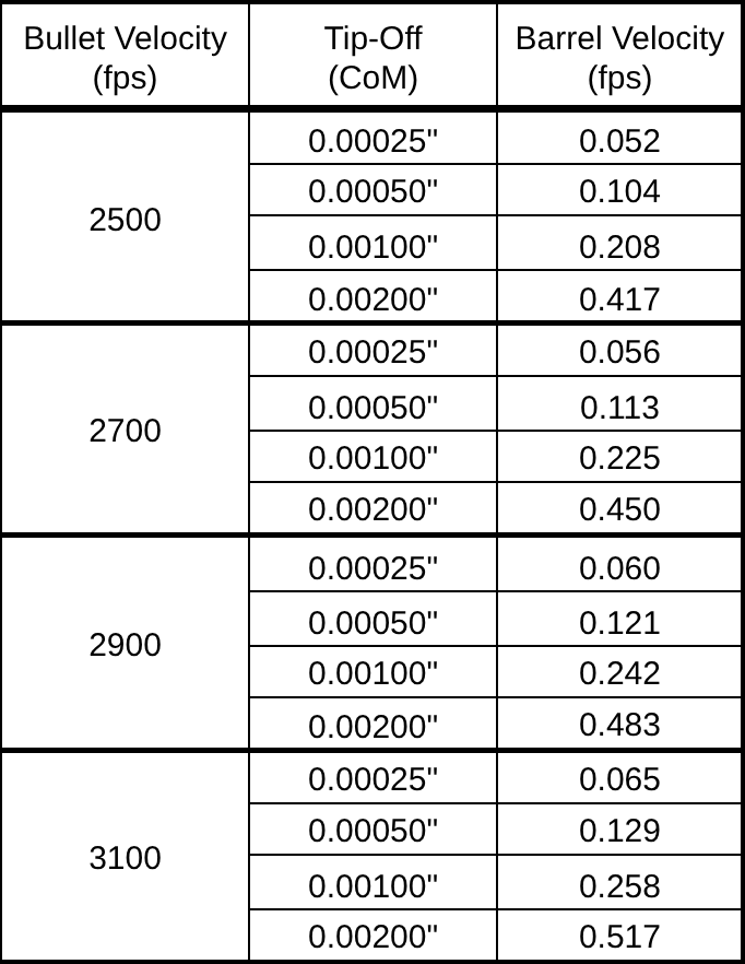
This proves barrel whip does not need to boast large amplitudes. Rather it is about timed micro-movements (appreciated in load development) during the bullet’s exit. In section 1.8 Observable Harmonics, we introduced barrel flexion values as low as 0.001″. While these deflections seem negligible, even invisible to high-speed cameras per section 1.9 Instrumental Proof, the ballistic tables below uses this marker as reference to highlight various aerodynamic consequences due to BC degradation (ignoring POI shift from flexion alone).
Specifically, we examine the downrange performance difference between two .308 175gr SMK bullets identical in weight, shape, and muzzle velocity; however:
• Bullet / Ballistic Table 1 – Is perfectly aligned with its velocity vector and calculated trajectory arc with a BC 0.2650.
• Bullet / Ballistic Table 2 – Exits with just 0.0005″ of (CoM) tip-off, resulting in a 0.4% BC reduction to net BC 0.2639.
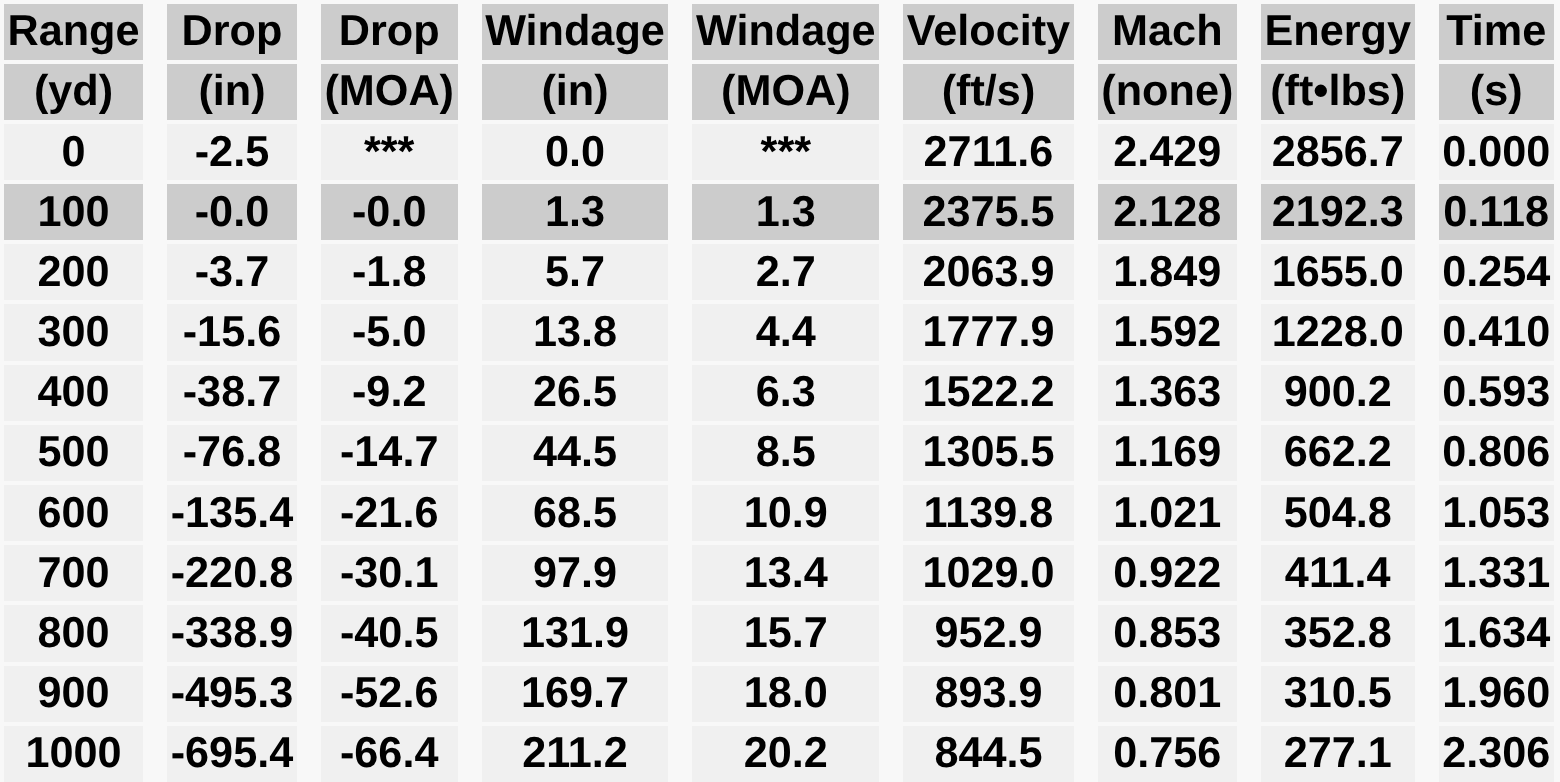
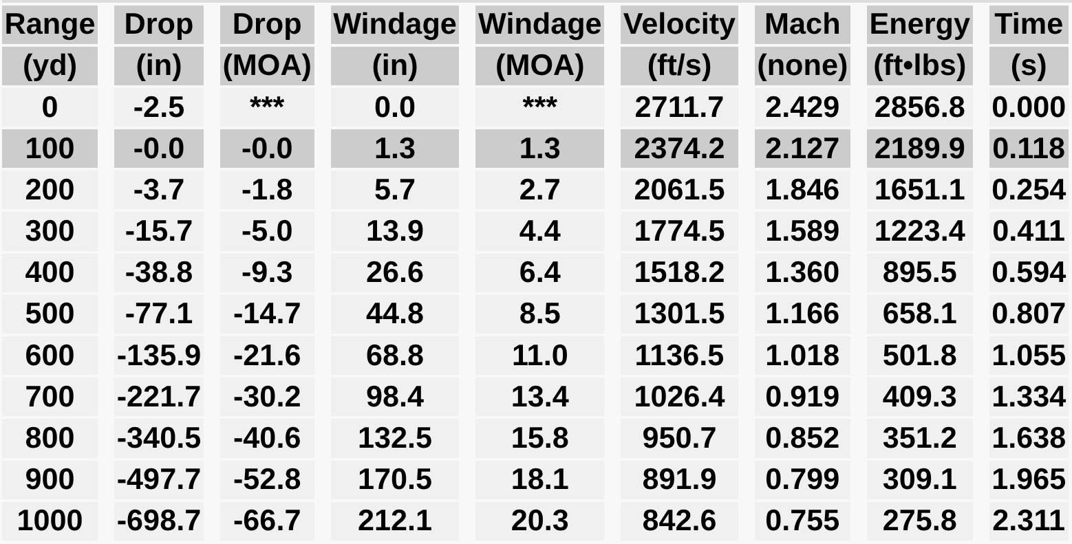
Even at the difference of just 0.4% in BC from a 0.0005″ tip-off yields 0.3 MOA or 3.3″ of more bullet drop at 1,000 yds, which could be the difference making podium.This data proves three critical ideas:
- Precision at the muzzle drives results at distance.
- A tip-off moment or “barrel whip” does not need to be visible.
- Effects do not need to be clear at 100-yds to be present.
At TACOM HQ, we harness immense surface area and structural rigidity to unlock new performance standards and to account for variable change.
© TACOM HQ, Inc. All rights reserved.
This website and all associated content, technical models, and innovations are the original work and intellectual property of TACOM HQ, Inc.
No part of this site may be reproduced, copied, stored, transmitted, or distributed in any form or by any means — electronic, mechanical, photocopying, recording, or otherwise — without the express written permission of TACOM HQ, Inc., except in the case of brief quotations used for review, academic reference, or critical analysis.
This content may not be copied, scraped, or used to train commercial AI systems without the prior written consent of TACOM HQ, Inc. Educational or research-based use is welcomed, provided proper attribution is given and the original context is preserved.

Made in the U.S.A.